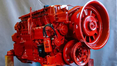
Mobile Crane LTM 1060/2 and Liebherr D926 TI-E A4 Engine
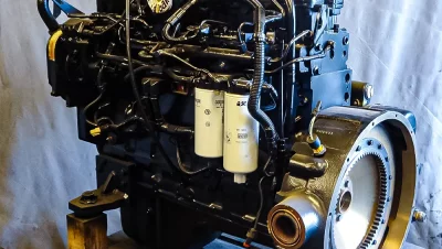
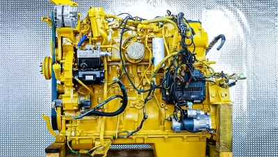
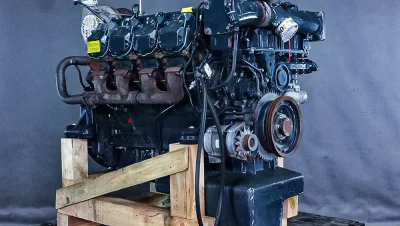
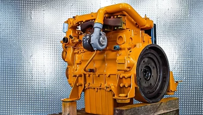
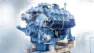
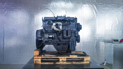
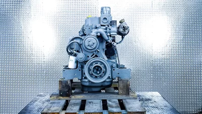
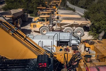
The mobile crane (all-terrain) LTM 1060/2 is a compact and versatile unit in the 60-ton class, valued for its precision handling, stability during operation on supports, and readiness for quick relocations between construction sites. In the discussed example, the drive is provided by a Liebherr D926 TI-E A4 with a power of 270 kW, a 6-cylinder turbocharged diesel engine designed for high operational culture and durability in off-highway applications. The Liebherr brand, as a manufacturer of both the machine and the engine, has been setting quality standards for years, and WIBAKO has been specializing in their comprehensive service for years.
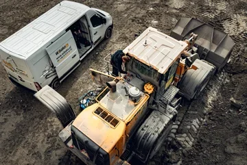
The LTM 1060/2 arrived at our service center, having been used on infrastructure projects in the Małopolskie Voivodeship. Due to the investor's work schedule, we performed preliminary diagnostic actions in the field, near Kraków, and then organized the transport of the power unit to our headquarters in Kojszówka. Our mobile service performed disassembly and secured all connections so that the machine itself could be prepared for service downtime.
The reason for the order was a clear loss of oil pressure and metallic noises that intensified after prolonged operation under increased load. We initially classified the case as wear of the crankshaft and connecting rod bearings with the risk of secondary damage to the crank-piston system. Below we present the complete scope of performed activities: from diagnostics, through repair and testing on our engine test bench, to assembly and handover of the crane for operation.
Preliminary Diagnostics in the Machine
We started by analyzing the operating history, checking the oil level and condition, and verifying the current readings of the lubrication system. The measured oil pressure on the warmed-up engine was below reference values. The operator reported episodic power drops and brief "knocking" under load. To confirm the hypothesis, we measured the oil pressure on an independent manometer and then took an oil sample for analysis. We recorded the engine's background noise with an acoustic probe, which facilitated locating the source of the noises around the main and connecting rod bearings.
We also performed basic cold and hot compression tests. The results indicated discrepancies between cylinders, but without clear signs of valve burning. The sum of the premises led us to the decision to disassemble the unit and perform a full internal verification, focusing on the crankshaft, connecting rods, and lubrication system (oil channels, oil pump, relief valve).
Engine Disassembly from the LTM 1060/2 Crane
The disassembly was carried out in the field using a crane provided by the client, following the procedure: disconnecting the batteries, draining and securing operating fluids, disassembling auxiliary equipment (intake and exhaust systems, fuel lines, oil and cooling lines), disconnecting the clutch and mounting brackets. We marked electrical connections and sensors to shorten the time of later assembly. We paid special attention to sealing and capping the cooling and intake system ports to avoid contamination during transport. The engine was safely removed, placed on a transport frame, and then transported to our workshop in Kojszówka.
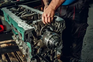
Verification of Components in the Workshop
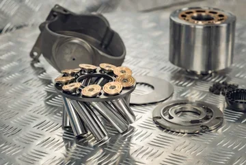
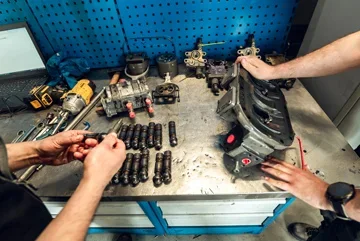
At the verification stage, we started by disassembling the oil pan and inspecting for the presence of metal shavings. We confirmed significant signs of wear on the connecting rod bearings and discoloration on the crank pins, indicating local overheating. We measured the crankshaft runout, measured the main and connecting rod pins, checked the oil channels, and inspected the connecting rods (twisting, longitudinal bending, screw threads). We examined the play on the turbocharger and verified the injection pump and injectors on the test bench. The cylinder head underwent a leak test in a water bath with compressed air and standard measurements of valve guide clearances and seat conditions.
Result: preliminary diagnosis confirmed. The source of the problem was wear of the bearings accompanied by signs of overheating of the crank pins, which posed a risk of further escalation of damage if work continued.
Regeneration and Repair
Crank-Piston System
We carried out a complete rebuild: grinding the crankshaft to repair dimensions at a specialized facility, cleaning and flushing the oil channels, checking and selecting main and connecting rod bearings, weighing the connecting rods, replacing piston rings and cylinder liners as specified in the documentation. We used new connecting rod bolts of the appropriate class, and the tightening torques were executed according to the manufacturer's service sequence.
Engine Head
The head was planed, received new valve guides and valves. We machined the seats and performed a leak test. We installed new stem seals and checked the valve springs. We used a new head gasket of the appropriate thickness after measuring the piston protrusion above the block.
Fuel System
The injection pump, after verification on the test bench, was adjusted, and the injectors were calibrated for opening and atomization pressures. We replaced high and low-pressure lines, and we refreshed the fuel filtration with OEM quality filter sets.
Auxiliary Equipment
We checked the turbocharger for longitudinal and transverse play, the tightness of the intake and exhaust systems, the alternator, starter, and electrical harness. We replaced worn oil and water lines, checked the tensioner and auxiliary belt. The entire system was complemented by a new water pump and thermostat to restore nominal cooling characteristics.
Professional Assembly
We assembled the unit in workshop conditions while maintaining cleanliness and dimensional control procedures. Each critical thread was prepared, and connections were tightened with a torque wrench according to specifications. We ensured proper sealing of covers and ports, and the lubrication system was filled with oil compliant with the manufacturer's standard.
Testing on WIBAKO Engine Test Bench
One of the key elements of our service is testing on the engine test bench. As one of the few companies in the region, we have a station that allows us to load the engine under controlled conditions even before installation in the machine. This allows us to verify real parameters: achieved power and torque, oil pressure stability, coolant and oil temperature, smoke emissions, and behavior under multiple load changes.
After initial running-in under light load (about 20-30% of nominal power) for a minimum of 16 operating hours, we proceeded to full load tests. We checked the repeatability of performance across the entire range of engine speeds, response to rapid load increases, and stability at idle after test cycles. We recorded operating parameters in real-time, and the results were compared with reference values for the D926 TI-E A4. During the tests, we verified the tightness of the systems and the absence of unwanted noises or vibrations.
The test bench allows us to detect faults that may remain invisible in garage conditions: minor leaks under load, incorrect fuel dosage adjustment at specific RPMs, or drops in oil pressure after prolonged operation cycles. As a result, the client receives an engine ready for installation and immediate operation, minimizing the risk of technological interruptions on the construction site. Additionally, we prepare a test report with a graph of power and torque curves, which serves as documentation and warranty value.
Engine Installation in the LTM 1060/2 Crane
The installation was carried out at the client's site, using a site crane provided by the investor. We started by preparing the engine compartment: cleaning, inspecting the mounts and frame, checking the mounting sockets, and replacing flexible elements where wear was detected. The engine was introduced into the compartment while maintaining the required installation clearances, and we positioned it relative to the clutch and transmission using alignment tools to ensure co-axiality and reduce vibrations during further operation.
After mechanically positioning the engine, we proceeded to recreate the piping: intake and exhaust lines, oil and cooling lines, and fuel installation. We used new clamps, brackets, and seals, and all connections were subjected to a leak test. We routed the electrical harness according to the original paths, protecting critical sections from abrasion and temperature. We filled the cooling system with fresh fluid with the appropriate parameters, performing bleeding and pressure testing. We replaced oil, fuel, and air filters, and we filled the oil according to the selection chart.
The start-up took place in the presence of the operator. In the first phase, we monitored oil pressure, temperature, and operational sound, then conducted a series of functional tests of the crane at various engine speeds. We checked the transition from idle to working ranges, behavior under full hydraulic load, and responses to sudden changes in power demand. We ensured a leak inspection after heating and cooling the assembly, which allows us to detect minor leaks that often only reveal themselves after thermal cycles.
After positive tests, we prepared an installation report and provided the operator with operational guidelines for the running-in period. As a result, the LTM 1060/2 could return to work without unnecessary delay, and the client received a complete documentation package along with service recommendations.
Engine Maintenance After Repair
All engines after repair at WIBAKO are covered by a warranty and can be further serviced by our service. We recommend the first filter change after 50 operating hours from start-up and a review of connections between the engine and other components. Subsequent reviews should occur every 250 operating hours, but no less than every 3 months. During this period, we check, among other things, the tightness of the systems, the condition of fluids, belt tension, the state of mounts, and calibration of current parameters. This approach minimizes the risk of unplanned downtimes and ensures performance levels close to factory specifications.
Where the Liebherr D926 TI-E A4 Engine is Used
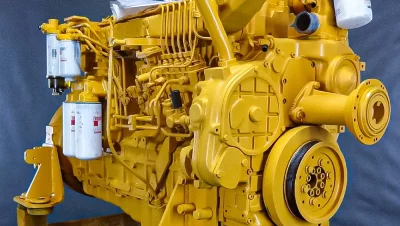
The D926 TI-E A4 unit in the 270 kW variant is found in selected Liebherr machines, including mobile cranes of the LTM series and construction machines of this brand, depending on the year of manufacture and configuration. Our technical department always verifies serial numbers and equipment variants at the inquiry stage to accurately select parts and the scope of adjustments. In practice, this allows us to shorten repair time and increase predictability of the final effect.
Summary of Benefits for the Client
The repair of the Liebherr D926 TI-E A4 engine in the LTM 1060/2 crane included a complete verification, rebuilding of the crank-piston system, regeneration of the head, checking the fuel system and auxiliary equipment, testing on the engine test bench, and professional installation in the machine. As a result, the client gained assurance of operating parameters before installation, shorter start-up time on the construction site, and reduced risk of secondary failures. Our mobile service travels to the machine's work site, and we test and prepare the unit in Kojszówka. After completing the work, we provide operational instructions and remind about the review after 50 operating hours, which our service performs at the client’s location.