

Construction Machinery Service
Professional Hydraulic System Repairs, Diesel Engine Overhauls and Mobile Service
-
Telefon
+48 33 870 42 00
Zadzwoń -
WhatsApp
+48 532 161 000
Napisz na WhatsApp -
E-mail
biuro@wibako.pl
Wyślij e-mail
Diagnostics of LICCON system error codes - Liebherr LTM-1070-4.1 Crane
The Liebherr LTM-1070-4.1 mobile crane is equipped with an advanced LICCON control and diagnostic system. This system continuously monitors operating parameters of hydraulic and electrical components, safety sensors (LMB), and the LSB/CAN data bus. In case of abnormalities, central computers generate detailed error codes stored in the diagnostic log.
The following catalog contains a list of LICCON system error codes for the Liebherr LTM-1070-4.1 model. The tips facilitate quick fault identification, indicate the appropriate plug connectors, and recommended repair procedures.
Professional internal combustion engine overhauls
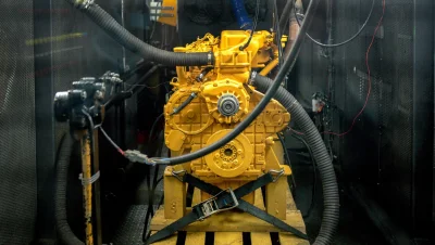
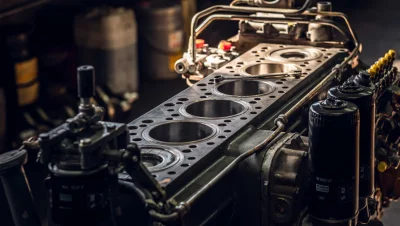
We perform comprehensive major and partial overhauls of internal combustion engines from renowned brands such as Liebherr, Caterpillar, Perkins, Cummins, or Deutz. We offer complete computer diagnostics, precise component reconditioning, and parameter verification on an engine dynamometer. Thanks to our own spare parts warehouse and mobile service option with unit disassembly at the customer's site, we reduce your machine's downtime to a minimum. We provide a 12-month warranty for every completed service, giving you confidence in reliability under the toughest conditions.
LICCON Error Code Catalog
| Error Code | Error Description / System Reaction / Repair Procedure | Plug | C | S |
|---|---|---|---|---|
| M00039801 | ZE 0: diagnostic system operation - interruption, master switch defective or missing Interrupts or delays test program execution. Check master switch and rerun test. |
- | B | 1 |
| M00039802 | ZE 0: diagnostic system operation - interruption, incorrect or missing operating mode Set correct operating mode, if necessary remove additional equipment and repeat test. |
- | B | 1 |
| M00039803 | ZE 0: diagnostic system operation - interruption, incorrect slewing mechanism locking state Unlock turntable or check slewing signals. |
- | B | 1 |
| M00039814 | ZE 0: diagnostic system operation - setup aid was not properly turned off Press F key to finish active test program. |
- | B | 1 |
| M00039820 | ZE 0: diagnostic system operation - boom angle out of allowable range Change angle to correct position and repeat test program. |
- | B | 1 |
| M00039821 | ZE 0: diagnostic system operation - telescope length out of allowable range Extend telescope to required length and retry test. |
- | B | 1 |
| M00039822 | ZE 0: diagnostic system operation - hook load out of allowable range Consider maximum hook load and perform test program again. |
- | B | 1 |
| M00039824 | ZE 0: diagnostic system operation - hoist limit switch active/defective/missing Check hoist limit switch and repeat program. |
- | B | 1 |
| M00100001 | ZE 1: system error OS-HC11 - processor register initialization error Crane operation impossible. If error recurs, replace ZE unit. |
- | E | 2 |
| M00100002 | ZE 1: system error OS-HC11 - EPROM/FLASH checksum error Crane operation impossible. Check program card or ZE unit. |
- | E | 2 |
| M00100006 | ZE 1: system error OS-HC11 - RAM initialization error Crane operation impossible. In case of recurring fault, replace ZE. |
- | E | 2 |
| M00100007 | ZE 1: system error OS-HC11 - UART interface error Crane operation impossible. Replace ZE central unit. |
- | E | 2 |
| M00100010 | ZE 1: system error OS-HC11 - system procedure unavailable Error memory log, all crane movements stopped. |
- | E | 2 |
| M00100011 | ZE 1: system error OS-HC11 - ZE watchdog timeout Stop crane movements. Check ZE module. |
- | E | 2 |
| M00100012 | ZE 1: system error OS-HC11 - incorrect type identification in EPROM Check program memory card. Crane operation impossible. |
- | E | 2 |
| M00100013 | ZE 1: system error OS-HC11 – FLASH memory checksum error Check LICCON program card. Machine movements stopped. |
- | E | 2 |
| M00100014 | ZE 1: system error OS-HC11 - program already running Error log entry, working movements stopped. |
- | E | 2 |
| M00100015 | ZE 1: system error OS-HC11 - program unavailable Error log entry, crane operation stopped. |
- | E | 2 |
| M00100016 | ZE 1: system error OS-HC11 - system driver watchdog exceeded All crane movements are stopped. |
- | E | 2 |
| M00100017 | ZE 1: system error OS-HC11 - total CPU allocation time too high ZE 1 computer operation interrupted, movements suspended. |
- | E | 2 |
| M00100018 | ZE 1: system error OS-HC11 - arithmetic overflow (16 Bit) Log entry, system stop. |
- | E | 2 |
| M00100019 | ZE 1: system error OS-HC11 - division by zero Program calculation error, operation stop. |
- | E | 2 |
| M00100020 | ZE 1: system error OS-HC11 - task watchdog timeout Crane movements stopped. |
- | E | 2 |
| M00100021 | ZE 1: system error OS-HC11 - illegal CPU instruction (illegal opcode) Replace ZE 1 board if error recurs regularly. |
- | E | 2 |
| M00100022 | ZE 1: system error OS-HC11 - task inactive All crane movements suspended. |
- | E | 2 |
| M00100023 | ZE 1: system error OS-HC11 - program unable to start Check software compatibility and type identifier. |
- | E | 2 |
| M00100024 | ZE 1: system error OS-HC11 - task already in use Driver process overlap error. |
- | E | 2 |
| M00100025 | ZE 1: system error OS-HC11 - real-time module already busy Hydraulic operations stopped. |
- | E | 2 |
| M00100026 | ZE 1: system error OS-HC11 - controller module already in use Error memory entry, control shutdown. |
- | E | 2 |
| M00100030 | ZE 1: system error OS-HC11 - unacceptable memory bank address LICCON control system stopped. |
- | E | 2 |
| M00100041 | ZE 1: system error OS-HC11 - processor arithmetic error All crane movements are stopped. |
- | E | 2 |
| M00100044 | ZE 1: system error OS-HC11 - output parameter without effect from inactive output Operating system stopped. |
- | E | 2 |
| M00100045 | ZE 1: system error OS-HC11 - input parameter undefined from inactive input Working movements stopped. |
- | E | 2 |
| M00100046 | ZE 1: system error OS-HC11 - invalid controller parameter Check software configuration. |
- | E | 2 |
| M00100047 | ZE 1: system error OS-HC11 - real-time control block unavailable Machine movements stopped. |
- | E | 2 |
| M00100048 | ZE 1: system error OS-HC11 - real-time control block inactive All movements suspended. |
- | E | 2 |
| M00100049 | ZE 1: system error OS-HC11 - urgent module unavailable in ZE Crane operation impossible. Check/replace ZE 1. |
- | E | 2 |
| M00100050 | ZE 1: system error OS-HC11 - file unavailable Required file missing in system memory. |
- | E | 2 |
| M00100051 | ZE 1: system error OS-HC11 - file already open Crane working movements stopped. |
- | E | 2 |
| M00100052 | ZE 1: system error OS-HC11 - file was not open when attempting to close Internal control software error. |
- | E | 2 |
| M00100053 | ZE 1: system error OS-HC11 - system mask unavailable Crane operations stopped. |
- | E | 2 |
| M00100054 | ZE 1: system error OS-HC11 - system text unavailable Crane movements stopped. |
- | E | 2 |
| M00100055 | ZE 1: system error OS-HC11 - symbol unavailable Screen data structure error. |
- | E | 2 |
| M00100056 | ZE 1: system error OS-HC11 - invalid tag in symbol Error log entry. Movements stopped. |
- | E | 2 |
| M00100057 | ZE 1: system error OS-HC11 - missing default load chart table Crane movements stopped. Upload proper load chart tables. |
- | E | 2 |
| M00100058 | ZE 1: system error OS-HC11 - damaged amplifier or feedback power supply Check wiring and electrical connections. |
- | E | 2 |
| M00100059 | ZE 1: system error OS-HC11 - subroutine is not reentrant All working movements stopped. |
- | E | 2 |
| M00100060 | ZE 1: system error OS-HC11 - SCI transmission error Check ZE control monitor and connection cable. |
- | E | 2 |
| M00100061 | ZE 1: system error OS-HC11 - SCI-BREAK signal Check connection between monitor and central unit. |
- | E | 2 |
| M00100062 | ZE 1: system error OS-HC11 - SCI interface not connected Check plugs and signal bus cable of the monitor. |
- | E | 2 |
| M00100063 | ZE 1: system error OS-HC11 - monitor error during operation Check power supply and status of LICCON control monitor. |
- | E | 2 |
| M00100065 | ZE 1: system error OS-HC11 - illegal bus address Crane operations stopped. |
- | E | 2 |
| M00100066 | ZE 1: system error OS-HC11 - ADC converter operating out of tolerance Replace ZE 1 unit if problem persists. |
- | E | 2 |
| M00100067 | ZE 1: system error OS-HC11 - arithmetic coprocessor unavailable Working movements stopped. Replace ZE 1 module. |
- | E | 2 |
| M00100068 | ZE 1: system error OS-HC11 - illegal hardware interrupt If fault recurs, ZE 1 replacement is necessary. |
- | E | 2 |
| M00100070 | ZE 1: system error OS-HC11 - incompatible software structure versions Crane operation impossible. Update software. |
- | E | 2 |
| M00100071 | ZE 1: system error OS-HC11 - missing or damaged structure file Upload proper configuration files to controller memory. |
- | E | 2 |
| M00100072 | ZE 1: system error OS-HC11 - nonsensical entry in data structure Machine operation blocked. Reconfigure system. |
- | E | 2 |
| M00100073 | ZE 1: system error OS-HC11 - code interpreter error Machine movements stopped. |
- | E | 2 |
| M00100074 | ZE 1: system error OS-HC11 - ASCII to BIN data conversion error Crane operation control shut down. |
- | E | 2 |
| M00100075 | ZE 1: system error OS-HC11 - SPI bus error Replace ZE 1 unit if error recurs. |
- | E | 2 |
| M00100076 | ZE 1: system error OS-HC11 - improperly inserted power supply / power module Check memory card in power supply unit. |
- | E | 2 |
| M00100077 | ZE 1: system error OS-HC11 - faulty BAF function call Working movements stopped. |
- | E | 2 |
| M00100078 | ZE 1: system error OS-HC11 - illegal call parameter Task execution interrupted in ZE 1. |
- | E | 2 |
| M00100079 | ZE 1: system error OS-HC11 - missing access rights to resource Crane movements stopped. |
- | E | 2 |
| M00100080 | ZE 1: system error OS-HC11 - Fatal internal error Control stopped. Reset machine power. |
- | E | 2 |
| M00100081 | ZE 1: system error OS-HC11 - stack overflow Working movements shut down. |
- | E | 2 |
| M00100082 | ZE 1: system error OS-HC11 - hardware watchdog error Replace ZE 1 main board. |
- | E | 2 |
| M00100094 | ZE 1: system error OS-HC11 - parallel bus transmission error Check ZE, bus board, and power supply. |
- | E | 2 |
| M00100095 | ZE 1: system error OS-HC11 - DMA controller error Check bus board and power supply connections. |
- | E | 2 |
| M00100099 | ZE 1: system error OS-HC11 - DSPO digital processor damage In case of recurrence, replace ZE 1. |
- | E | 2 |
| M00102001 | ZE 1: system error OS-TMS - TMS processor register initialization error Crane movements stopped. ZE 1 replacement required. |
- | E | 2 |
| M00102002 | ZE 1: system error OS-TMS - EPROM/FLASH checksum error Replacement of ZE 1 main board required. |
- | E | 2 |
| M00102006 | ZE 1: system error OS-TMS - auxiliary processor RAM error Replace ZE 1 controller. |
- | E | 2 |
| M00102007 | ZE 1: system error OS-TMS - UART module fault Operation stopped. Replace ZE 1. |
- | E | 2 |
| M00102020 | ZE 1: system error OS-TMS - TMS processor watchdog timeout Stop machine. Fault clearance possible only by authorized service. |
- | E | 2 |
| M00102021 | ZE 1: system error OS-TMS - illegal opcode trap Factory service intervention required. |
- | E | 2 |
| M00102082 | ZE 1: system error OS-TMS - hardware safety switch fault Repair exclusively by authorized factory service. |
- | E | 2 |
Comprehensive repair and reconditioning of power hydraulics
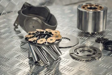
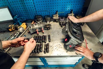
We specialize in professional repair and reconditioning of power hydraulic components, including hydraulic pumps, motors, control valves, and cylinders. Each component undergoes precise diagnostics on specialized test benches, allowing quick fault detection and restoration of factory operating parameters. Thanks to a large stock of spare parts and mobile service capability directly to the construction site, we effectively eliminate costly equipment downtime. All repaired components are tested under load and covered by a full warranty, ensuring their trouble-free operation in harsh conditions.
LICCON Error Code Catalog
| Error Code | Error Description / System Reaction / Repair Procedure | Plug | C | S |
|---|---|---|---|---|
| M00110012 | ZE 1: output 0 - short circuit to ground Check signal line for short circuit to ground. |
X71:16 | E | 1 |
| M00110013 | ZE 1: output 0 - open circuit in signal line Check wire, plug, and receiver coil. |
X71:16 | E | 1 |
| M00110014 | ZE 1: output 0 - short circuit to supply voltage Locate short circuit in electrical system. |
X71:16 | E | 1 |
| M00110054 | ZE 1: output 0 - short circuit to supply voltage Inspect output circuit X71 pin 16. |
X71:16 | E | 1 |
| M00110058 | ZE 1: output 0 - positive switching transistor: open Transistor damage on controller output board. |
X71:16 | E | 1 |
| M00110070 | ZE 1: output 0 - measurement system damage Crane operation impossible. Error log entry. |
X71:16 | E | 1 |
| M00110071 | ZE 1: output 0 - short circuit to ground or output transistor damage Verification of power stage transistor or wiring harness. |
X71:16 | E | 1 |
| M00110072 | ZE 1: output 0 - power supply from external source Foreign voltage detected at module output. |
X71:16 | E | 1 |
| M00110073 | ZE 1: output 0 - open circuit or short circuit to supply/ground Check complete current circuit of terminal X71:16. |
X71:16 | E | 1 |
| M00110112 | ZE 1: output 1 - short circuit to ground Check output circuit on connector X71 pin 17. |
X71:17 | E | 1 |
| M00110113 | ZE 1: output 1 - open circuit in signal wire Defective coil or broken cable. |
X71:17 | E | 1 |
| M00110114 | ZE 1: output 1 - short circuit to supply (+24V) Eliminate short circuit in system. |
X71:17 | E | 1 |
| M00110154 | ZE 1: output 1 - short circuit to supply voltage Incorrect voltage applied to pin X71:17. |
X71:17 | E | 1 |
| M00110158 | ZE 1: output 1 - switching transistor damage Replacement of controller output board. |
X71:17 | E | 1 |
| M00110170 | ZE 1: output 1 - fault in output current measurement system Crane operation impossible. |
X71:17 | E | 1 |
| M00110171 | ZE 1: output 1 - short circuit to ground or mfet transistor damage Check wire insulation state to receiver. |
X71:17 | E | 1 |
| M00110172 | ZE 1: output 1 - external power supply to output circuit Disconnect improper power source from circuit. |
X71:17 | E | 1 |
| M00110173 | ZE 1: output 1 - open circuit or short circuit supply/ground Verification of cable harness at connector X71:17. |
X71:17 | E | 1 |
| M00110212 | ZE 1: output 2 - signal short circuit to ground Check load wires on X71 pin 18. |
X71:18 | E | 1 |
| M00110213 | ZE 1: output 2 - broken wire or plug No electrical continuity to coil. |
X71:18 | E | 1 |
| M00110214 | ZE 1: output 2 - short circuit to positive potential Check system for insulation damage. |
X71:18 | E | 1 |
| M00110254 | ZE 1: output 2 - output short circuit to supply Check output circuit X71:18. |
X71:18 | E | 1 |
| M00110258 | ZE 1: output 2 - switching transistor open Damaged module output transistor. |
X71:18 | E | 1 |
| M00110260 | ZE 1: output 2 - safety chain error, damaged diode or stuck contact Error message without immediate reaction. Check diode and relay contact. |
X71:18 | E | 1 |
| M00110270 | ZE 1: output 2 - output measurement system defect Crane operation suspended, error in log. |
X71:18 | E | 1 |
| M00110271 | ZE 1: output 2 - short circuit to ground or defective transistor Check actuator element and transistor condition. |
X71:18 | E | 1 |
| M00110272 | ZE 1: output 2 - external power supply detected Inspect power supply connections in junction box. |
X71:18 | E | 1 |
| M00110273 | ZE 1: output 2 - open circuit or line-ground/supply short circuit Resistance measurements of wiring harness X71:18. |
X71:18 | E | 1 |
| M00110312 | ZE 1: output 3 - short circuit to negative pole (ground) Check wire leading to X71:19. |
X71:19 | E | 1 |
| M00110313 | ZE 1: output 3 - open output circuit Check solenoid valve circuit continuity. |
X71:19 | E | 1 |
| M00110314 | ZE 1: output 3 - short circuit to circuit power supply Check power supply harness at connector X71:19. |
X71:19 | E | 1 |
| M00110354 | ZE 1: output 3 - circuit shorted to positive voltage Locate short circuit location in rotary harness. |
X71:19 | E | 1 |
| M00110358 | ZE 1: output 3 - switching transistor: damage/open Controller repair or ZE 1 board replacement. |
X71:19 | E | 1 |
| M00110360 | ZE 1: output 3 - safety chain error, diode or relay contact Check safety relay and protection diode. |
X71:19 | E | 1 |
| M00110370 | ZE 1: output 3 - load current measurement system error Crane operation suspended. |
X71:19 | E | 1 |
| M00110371 | ZE 1: output 3 - short circuit to ground or output transistor damage Verification of power transistor functionality. |
X71:19 | E | 1 |
| M00110372 | ZE 1: output 3 - external power source connection Check correct connection of attachments. |
X71:19 | E | 1 |
| M00110373 | ZE 1: output 3 - open circuit or supply/ground short circuit Inspection of electrical connections on pin X71:19. |
X71:19 | E | 1 |
| M00110412 | ZE 1: output 4 - short circuit to system ground Check output circuit connected to X71 pin 20. |
X71:20 | E | 1 |
| M00110413 | ZE 1: output 4 - open circuit in load supply wire Check plug condition and wire continuity. |
X71:20 | E | 1 |
| M00110414 | ZE 1: output 4 - signal short circuit to supply voltage Eliminate short circuit of wire X71:20 with +24V potential. |
X71:20 | E | 1 |
| M00110454 | ZE 1: output 4 - short circuit of output signal to supply Verification of power harness. |
X71:20 | E | 1 |
| M00110458 | ZE 1: output 4 - positive control transistor open Hardware damage of ZE 1 module. |
X71:20 | E | 1 |
| M00110460 | ZE 1: output 4 - safety circuit, diode, or contacts fault Check if relay contact is not stuck. |
X71:20 | E | 1 |
| M00110470 | ZE 1: output 4 - controller measurement circuit damage Motion control impossible. |
X71:20 | E | 1 |
| M00110471 | ZE 1: output 4 - short circuit to ground or output transistor damage Inspect receiver connected to X71:20. |
X71:20 | E | 1 |
| M00110472 | ZE 1: output 4 - external voltage applied to output pin Disconnect improper external power supply. |
X71:20 | E | 1 |
| M00110473 | ZE 1: output 4 - open circuit or signal short circuit Detailed inspection of connector X71:20. |
X71:20 | E | 1 |
| M00110512 | ZE 1: output 5 - short circuit to operating ground Check cable on connector X71 pin 21. |
X71:21 | E | 1 |
| M00110513 | ZE 1: output 5 - no closed circuit (open) No connection to solenoid valve coil detected. |
X71:21 | E | 1 |
| M00110514 | ZE 1: output 5 - short circuit to supply voltage Locate insulation damage in circuit X71:21. |
X71:21 | E | 1 |
| M00110554 | ZE 1: output 5 - short circuit to positive voltage Inspect cable harness. |
X71:21 | E | 1 |
| M00110558 | ZE 1: output 5 - output switching transistor damaged Repair of ZE 1 output board required. |
X71:21 | E | 1 |
| M00110560 | ZE 1: output 5 - safety chain error or welded contact Check output circuit protection components. |
X71:21 | E | 1 |
| M00110570 | ZE 1: output 5 - faulty operation of measurement converter Stop machine, read parameters. |
X71:21 | E | 1 |
| M00110571 | ZE 1: output 5 - short circuit to ground or transistor breakdown Inspection of harness and power stage functionality. |
X71:21 | E | 1 |
| M00110572 | ZE 1: output 5 - foreign power supply detected at output Eliminate connection to foreign power source. |
X71:21 | E | 1 |
| M00110573 | ZE 1: output 5 - open circuit or line-ground/supply short circuit Check current continuity of pin X71:21 circuit. |
X71:21 | E | 1 |
| M00110612 | ZE 1: output 6 - short circuit to ground Check wire to terminal X71 pin 22. |
X71:22 | E | 1 |
| M00110613 | ZE 1: output 6 - open current circuit Damaged coil or unplugged connector at valve. |
X71:22 | E | 1 |
| M00110614 | ZE 1: output 6 - short circuit to positive potential (+24V) Eliminate short circuit in electrical system. |
X71:22 | E | 1 |
| M00110654 | ZE 1: output 6 - short circuit of signal to supply Inspect harness at connector X71:22. |
X71:22 | E | 1 |
| M00110658 | ZE 1: output 6 - open in power switching transistor Replace damaged ZE 1 output module. |
X71:22 | E | 1 |
| M00110660 | ZE 1: output 6 - safety chain error, diode or relay contact Inspect output relay and semiconductor components. |
X71:22 | E | 1 |
| M00110670 | ZE 1: output 6 - output load measurement circuit damage Crane locked, no movement possible. |
X71:22 | E | 1 |
| M00110671 | ZE 1: output 6 - short circuit to ground or defective power transistor Inspection of receiver circuit connected to X71:22. |
X71:22 | E | 1 |
| M00110672 | ZE 1: output 6 - power supply from foreign electrical circuit Eliminate improper power supply jumper. |
X71:22 | E | 1 |
| M00110673 | ZE 1: output 6 - open circuit or short circuit supply/ground Perform current measurement on connector X71:22. |
X71:22 | E | 1 |
| M00110712 | ZE 1: output 7 - short circuit to operating ground Check wire condition X71 pin 23. |
X71:23 | E | 1 |
| M00110713 | ZE 1: output 7 - open electrical circuit Check component connected under pin X71:23. |
X71:23 | E | 1 |
| M00110714 | ZE 1: output 7 - short circuit to supply voltage Find short circuit to battery positive pole. |
X71:23 | E | 1 |
| M00110754 | ZE 1: output 7 - short circuit to supply voltage Check conductivity of pin X71:23 to +24V. |
X71:23 | E | 1 |
| M00110758 | ZE 1: output 7 - positive switching transistor open Repair ZE 1 controller or replace module. |
X71:23 | E | 1 |
| M00110760 | ZE 1: output 7 - safety circuit defect, diode or stuck contact Check relay and protective circuit. |
X71:23 | E | 1 |
| M00110770 | ZE 1: output 7 - controller measurement system defect Stop crane, switch ignition off and on. |
X71:23 | E | 1 |
| M00110771 | ZE 1: output 7 - short circuit to ground or mfet transistor damage Verification of harness and connected coil. |
X71:23 | E | 1 |
| M00110772 | ZE 1: output 7 - power supply applied from foreign circuit Check electrical wiring diagram for foreign supplies. |
X71:23 | E | 1 |
| M00110773 | ZE 1: output 7 - open circuit or short circuit line-ground/supply Check continuity of cable cores on X71:23. |
X71:23 | E | 1 |
| M00114959 | ZE 1: no supply voltage to all outputs Check main fuses of controller and power supply relay on plug X71. |
X71 | E | 1 |
| M00115059 | ZE 1: no supply voltage to output group 0 Check power supply input on connector X71 pin 12. |
X71:12 | E | 1 |
| M00115159 | ZE 1: no supply voltage to output group 1 Check fuse and supply circuit X71 pin 24. |
X71:24 | E | 1 |
| M00115259 | ZE 1: no supply voltage to output group 2 Check power input to pin X71 pin 25. |
X71:25 | E | 1 |
| M00115359 | ZE 1: no supply voltage to output group 3 Check supply circuit of connector X71 pin 13. |
X71:13 | E | 1 |
Comprehensive repair and reconditioning of power hydraulics
We specialize in professional repair and reconditioning of power hydraulic components, including hydraulic pumps, motors, control valves, and cylinders. Each component undergoes precise diagnostics on specialized test benches, allowing quick fault detection and restoration of factory operating parameters. Thanks to a large stock of spare parts and mobile service capability directly to the construction site, we effectively eliminate costly equipment downtime. All repaired components are tested under load and covered by a full warranty, ensuring their trouble-free operation in harsh conditions.
LICCON Error Code Catalog
| Error Code | Error Description / System Reaction / Repair Procedure | Plug | C | S |
|---|---|---|---|---|
| M00120004 | ZE 1: LSB sensor address 0 - maximum value exceeded (level exceeded) Check mounting and pre-damping of sensor, clean dirt, replace damaged sensor. |
X635A:z14/z16 | E | 1 |
| M00120005 | ZE 1: LSB sensor address 0 - signal below minimum level Check sensor installation, remove blockage or damage, replace if necessary. |
X635A:z14/z16 | E | 1 |
| M00120018 | ZE 1: LSB sensor address 0 - excessive operating temperature Use sensor within allowable temperature range, inspect cooling/heat dissipation. |
X635A:z14/z16 | E | 0 |
| M00120050 | ZE 1: LSB sensor address 0 - reports incorrect sensor type Check address assignment in test system (LSB screen), install proper sensor. |
X635A:z14/z16 | E | 2 |
| M00120051 | ZE 1: LSB sensor address 0 - no configuration for block transfer Software configuration problem, load new control software. |
X635A:z14/z16 | E | 2 |
| M00120053 | ZE 1: LSB sensor address 0 - stopped responding or disconnected during operation Participant will be deactivated. Check connection, if cable OK - replace sensor. |
X635A:z14/z16 | E | 1 |
| M00120054 | ZE 1: LSB sensor address 0 - parameters differ from setpoint values Inspect parameter set on LSB screen, restore sensor default parameters. |
X635A:z14/z16 | E | 2 |
| M00120064 | ZE 1: LSB sensor address 0 - reports acceptable error in self-test Sensor operates properly. Check and clean sensor, replace if recurring. |
X635A:z14/z16 | E | 1 |
| M00120065 | ZE 1: LSB sensor address 0 - reports unacceptable self-test error Trouble-free operation not guaranteed. Replace sensor immediately. |
X635A:z14/z16 | E | 2 |
| M00120066 | ZE 1: LSB sensor address 0 - incompatible sensor software version System attempts to continue operation. Recommended to replace sensor with new type. |
X635A:z14/z16 | E | 2 |
| M00120067 | ZE 1: LSB sensor address 0 - no support for data download function Unable to update sensor software directly from ZE. |
X635A:z14/z16 | E | 1 |
| M00120104 | ZE 1: LSB sensor address 1 - maximum signal value exceeded Check address 1 sensor installation, clean dirt or replace element. |
X635A:z14/z16 | E | 1 |
| M00120105 | ZE 1: LSB sensor address 1 - signal value below minimum range Check electrical connectors and mechanical damage of sensor 1. |
X635A:z14/z16 | E | 1 |
| M00120118 | ZE 1: LSB sensor address 1 - operating temperature too high Ensure sensor operates within allowed temperature range. |
X635A:z14/z16 | E | 0 |
| M00120150 | ZE 1: LSB sensor address 1 - faulty transmitter type reported Verify addressing in LSB menu of LICCON computer. |
X635A:z14/z16 | E | 2 |
| M00120151 | ZE 1: LSB sensor address 1 - no transmission block configuration Upload correct system software to central unit. |
X635A:z14/z16 | E | 2 |
| M00120153 | ZE 1: LSB sensor address 1 - no response from sensor during operation Inspect power wires and data bus continuity. |
X635A:z14/z16 | E | 1 |
| M00120154 | ZE 1: LSB sensor address 1 - operating parameter setting error Set factory parameters of sensor via service menu. |
X635A:z14/z16 | E | 2 |
| M00120164 | ZE 1: LSB sensor address 1 - allowable error in self-test Clean sensor. If fault recurs - replace. |
X635A:z14/z16 | E | 1 |
| M00120165 | ZE 1: LSB sensor address 1 - critical self-test error of sensor Unstable operation. Replace sensor immediately with a new one. |
X635A:z14/z16 | E | 2 |
| M00120166 | ZE 1: LSB sensor address 1 - incompatible sensor software Use new sensor model compatible with LICCON version. |
X635A:z14/z16 | E | 2 |
| M00120167 | ZE 1: LSB sensor address 1 - no data download support No response, download operation impossible. |
X635A:z14/z16 | E | 1 |
| M00120804 | ZE 1: LSB sensor address 8 - max signal level exceeded Clean sensor, check mounting distance of sensor 8. |
X635A:z14/z16 | E | 1 |
| M00120805 | ZE 1: LSB sensor address 8 - signal below minimum level Check whether sensor has suffered mechanical damage. |
X635A:z14/z16 | E | 1 |
| M00120818 | ZE 1: LSB sensor address 8 - operating temperature exceeded Check thermal conditions around sensor housing. |
X635A:z14/z16 | E | 0 |
| M00120850 | ZE 1: LSB sensor address 8 - incorrect type reported Inspect address assignment in LSB menu. |
X635A:z14/z16 | E | 2 |
| M00120851 | ZE 1: LSB sensor address 8 - no block transmission configuration Load current system software into ZE 1. |
X635A:z14/z16 | E | 2 |
| M00120853 | ZE 1: LSB sensor address 8 - sensor disappeared from LSB bus Check cable harness continuity, plug connector X635A. |
X635A:z14/z16 | E | 1 |
| M00120854 | ZE 1: LSB sensor address 8 - invalid operating parameters Restore default settings of LSB transmitter. |
X635A:z14/z16 | E | 2 |
| M00120864 | ZE 1: LSB sensor address 8 - minor error in self-test Clean sensor, restart system power supply. |
X635A:z14/z16 | E | 1 |
| M00120865 | ZE 1: LSB sensor address 8 - self-test error excluding further operation Replace LSB sensor address 8 with a working one. |
X635A:z14/z16 | E | 2 |
| M00120866 | ZE 1: LSB sensor address 8 - incompatible software version Install original Liebherr sensor. |
X635A:z14/z16 | E | 2 |
| M00120867 | ZE 1: LSB sensor address 8 - no support for soft download No controller reaction, operation continued. |
X635A:z14/z16 | E | 1 |
| M00120904 | ZE 1: LSB sensor address 9 - signal level exceeded Clean sensor 9, ensure proper damping. |
X635A:z14/z16 | E | 1 |
| M00120905 | ZE 1: LSB sensor address 9 - signal value below allowable threshold Eliminate interruption in LSB sensor power supply. |
X635A:z14/z16 | E | 1 |
| M00120918 | ZE 1: LSB sensor address 9 - element temperature too high Check whether sensor is not located close to heat source. |
X635A:z14/z16 | E | 0 |
| M00120950 | ZE 1: LSB sensor address 9 - improper type reported Set proper characteristic on LSB screen. |
X635A:z14/z16 | E | 2 |
| M00120951 | ZE 1: LSB sensor address 9 - no data block configuration Upload corrected software version. |
X635A:z14/z16 | E | 2 |
| M00120953 | ZE 1: LSB sensor address 9 - signal loss/sensor disconnection Check bus cable on boom arm or jib. |
X635A:z14/z16 | E | 1 |
| M00120954 | ZE 1: LSB sensor address 9 - preset parameter mismatch Reset sensor to factory values. |
X635A:z14/z16 | E | 2 |
| M00120964 | ZE 1: LSB sensor address 9 - allowable self-test error Clean measuring surface of sensor 9. |
X635A:z14/z16 | E | 1 |
| M00120965 | ZE 1: LSB sensor address 9 - sensor damage error in internal test Replace LSB transmitter address 9 immediately. |
X635A:z14/z16 | E | 2 |
| M00120966 | ZE 1: LSB sensor address 9 - incompatible firmware Replace sensor with component matching catalog number. |
X635A:z14/z16 | E | 2 |
| M00120967 | ZE 1: LSB sensor address 9 - no soft download function Informational message, no effect on movements. |
X635A:z14/z16 | E | 1 |
| M00121004 | ZE 1: LSB sensor address 10 - max signal level exceeded Check installation of sensor 10, remove contamination. |
X635A:z14/z16 | E | 1 |
| M00121005 | ZE 1: LSB sensor address 10 - signal level below allowable min Inspect sensor supply circuit continuity. |
X635A:z14/z16 | E | 1 |
| M00121018 | ZE 1: LSB sensor address 10 - excessive operating temperature Maintain sensor within allowable temperature range. |
X635A:z14/z16 | E | 0 |
| M00121050 | ZE 1: LSB sensor address 10 - wrong reported sensor type Check sensor parameters in LSB test system. |
X635A:z14/z16 | E | 2 |
| M00121051 | ZE 1: LSB sensor address 10 - no data block configuration Load new software into computer ZE 1. |
X635A:z14/z16 | E | 2 |
| M00121053 | ZE 1: LSB sensor address 10 - no communication with sensor during operation Inspect connectors and signal cable of X635A connector. |
X635A:z14/z16 | E | 1 |
| M00121054 | ZE 1: LSB sensor address 10 - default parameter setting error Coordinate sensor parameters through service system. |
X635A:z14/z16 | E | 2 |
| M00121064 | ZE 1: LSB sensor address 10 - acceptable self-test error Clean sensor, reset controller. |
X635A:z14/z16 | E | 1 |
| M00121065 | ZE 1: LSB sensor address 10 - unacceptable error in self-test Sensor irreversibly damaged - replace element. |
X635A:z14/z16 | E | 2 |
| M00121066 | ZE 1: LSB sensor address 10 - incompatible sensor software Install verified sensor with correct index. |
X635A:z14/z16 | E | 2 |
| M00121067 | ZE 1: LSB sensor address 10 - software download unavailable No working reaction. |
X635A:z14/z16 | E | 1 |
| M00121104 | ZE 1: LSB sensor address 11 - signal level exceeded Check correct mounting and cleanliness of sensor. |
X635A:z14/z16 | E | 1 |
| M00121105 | ZE 1: LSB sensor address 11 - signal level too low Eliminate open circuit or voltage drop in sensor 11 circuit. |
X635A:z14/z16 | E | 1 |
| M00121118 | ZE 1: LSB sensor address 11 - excessive operating temperature Check temperature at installation site. |
X635A:z14/z16 | E | 0 |
| M00121150 | ZE 1: LSB sensor address 11 - wrong transmitter type assigned Adjust sensor parameters in LICCON software. |
X635A:z14/z16 | E | 2 |
| M00121151 | ZE 1: LSB sensor address 11 - no data block configuration Soft configuration problem, upload software. |
X635A:z14/z16 | E | 2 |
| M00121153 | ZE 1: LSB sensor address 11 - removed or no response from sensor Check connector connections and cable continuity. |
X635A:z14/z16 | E | 1 |
| M00121154 | ZE 1: LSB sensor address 11 - incorrect parameter configuration Reset sensor to factory settings. |
X635A:z14/z16 | E | 2 |
| M00121164 | ZE 1: LSB sensor address 11 - tolerated self-test error Perform cleaning and sensor inspection. |
X635A:z14/z16 | E | 1 |
| M00121165 | ZE 1: LSB sensor address 11 - no guarantee of proper operation (self-test failed) Replace LSB sensor address 11. |
X635A:z14/z16 | E | 2 |
| M00121166 | ZE 1: LSB sensor address 11 - incompatible software version Replace sensor with matching factory version. |
X635A:z14/z16 | E | 2 |
| M00121167 | ZE 1: LSB sensor address 11 - no data download support No reaction from system. |
X635A:z14/z16 | E | 1 |
| M00121204 | ZE 1: LSB sensor address 12 - signal level exceeded Check sensor 12 mounting and metal filing contamination. |
X635A:z14/z16 | E | 1 |
| M00121205 | ZE 1: LSB sensor address 12 - signal level below minimum Remove mechanical blockage or repair broken wire. |
X635A:z14/z16 | E | 1 |
| M00121218 | ZE 1: LSB sensor address 12 - excessive operating temperature Ensure proper temperature range for sensor. |
X635A:z14/z16 | E | 0 |
| M00121250 | ZE 1: LSB sensor address 12 - incorrect sensor type detected Check addressing in LSB test system. |
X635A:z14/z16 | E | 2 |
| M00121251 | ZE 1: LSB sensor address 12 - no data block configuration Upload correct control software. |
X635A:z14/z16 | E | 2 |
| M00121253 | ZE 1: LSB sensor address 12 - no response / sensor withdrawn Check cable connection of connector X635A. Replace sensor if harness undamaged. |
X635A:z14/z16 | E | 1 |
| M00121254 | ZE 1: LSB sensor address 12 - operating parameter configuration error Set default parameters on LSB service screen. |
X635A:z14/z16 | E | 2 |
| M00121264 | ZE 1: LSB sensor address 12 - tolerated error in self-test Perform inspection and cleaning of sensor. |
X635A:z14/z16 | E | 1 |
| M00121265 | ZE 1: LSB sensor address 12 - failed self-test (critical error) Replace LSB sensor address 12 immediately. |
X635A:z14/z16 | E | 2 |
| M00121266 | ZE 1: LSB sensor address 12 - incompatible sensor software Use genuine Liebherr spare part. |
X635A:z14/z16 | E | 2 |
| M00121267 | ZE 1: LSB sensor address 12 - software download unsupported Informational message in event memory. |
X635A:z14/z16 | E | 1 |
| M00121304 | ZE 1: LSB sensor address 13 - level exceeded Check mounting of sensor 13 for dirt. |
X635A:z14/z16 | E | 1 |
| M00121305 | ZE 1: LSB sensor address 13 - signal below minimum threshold Remove mechanical fault or open circuit in signal cable. |
X635A:z14/z16 | E | 1 |
| M00121318 | ZE 1: LSB sensor address 13 - high sensor temperature Operate within allowable temperature range. |
X635A:z14/z16 | E | 0 |
| M00121350 | ZE 1: LSB sensor address 13 - wrong sensor type reported Check address assignment in service program. |
X635A:z14/z16 | E | 2 |
| M00121351 | ZE 1: LSB sensor address 13 - no data block configuration Upload current software into ZE 1 unit. |
X635A:z14/z16 | E | 2 |
| M00121353 | ZE 1: LSB sensor address 13 - sensor stopped sending data Verification of cable harness and sensor socket. |
X635A:z14/z16 | E | 1 |
| M00121354 | ZE 1: LSB sensor address 13 - parameters differ from factory defaults Adjust parameters on LSB test screen. |
X635A:z14/z16 | E | 2 |
| M00121364 | ZE 1: LSB sensor address 13 - minor self-test error Inspect and clean sensor housing. |
X635A:z14/z16 | E | 1 |
| M00121365 | ZE 1: LSB sensor address 13 - severe self-test fault Replace LSB sensor address 13 with a new one. |
X635A:z14/z16 | E | 2 |
| M00121366 | ZE 1: LSB sensor address 13 - sensor software version error Replace sensor with proper generation element. |
X635A:z14/z16 | E | 2 |
| M00121367 | ZE 1: LSB sensor address 13 - no data download function No working response in LICCON system. |
X635A:z14/z16 | E | 1 |
| M00121404 | ZE 1: LSB sensor address 14 - max signal level exceeded Clean sensor 14 from contamination, check pre-damping. |
X635A:z14/z16 | E | 1 |
Construction equipment parts shop - original components and replacements
We offer a wide selection of original spare parts and verified replacements for construction machinery from renowned manufacturers such as Liebherr, Caterpillar, Komatsu, Volvo, or JCB. In our assortment you will find hydraulic, engine, drive, and chassis components available off-the-shelf from our own warehouse. Thanks to a fast order fulfillment process and shipping, we minimize your equipment downtime on site. Our expert team provides technical advice, helping to accurately select appropriate components by part number or VIN.
LICCON Error Code Catalog - Part 4 (ZE 1 Controller: Memory Drum, Data Recorder, and Telescoping Errors)
| Error Code | Error Description / System Reaction / Repair Procedure | Plug | C | S |
|---|---|---|---|---|
| M00123252 | ZE 1: LSB data transmission - bus collision detected, communication interrupted Controller withdraws from bus and restarts network. Check sensor addresses. |
X635A:z14/z16 | E | 0 |
| M00123255 | ZE 1: LSB transmission - connection damage, short circuit to supply voltage Controller attempts bus restart. Check LSB bus line, remove sensors one by one. |
X635A:z14/z16 | E | 2 |
| M00123256 | ZE 1: LSB transmission - bus damage, no power supply / short circuit to ground Check LSB cable, sensors, and bus fuse on board. |
X635A:z14/z16 | E | 2 |
| M00123257 | ZE 1: LSB transmission - network reset detected (reboot) Disconnect sensors from LSB bus sequentially to locate defective element. |
X635A:z14/z16 | E | 1 |
| M00123258 | ZE 1: LSB transmission - sensor with incorrect baudrate detected Cleared automatically by system. Check sensor addressing. |
X635A:z14/z16 | E | 0 |
| M00123259 | ZE 1: LSB transmission - damaged/kinked connections in bus Controller automatically restarts network to restore communication. |
X635A:z14/z16 | E | 0 |
| M00123260 | ZE 1: LSB transmission - driver error: no command to execute In case of false configuration, upload new system software. |
X635A:z14/z16 | E | 2 |
| M00123261 | ZE 1: LSB transmission - driver error: undefined message For permanent faults, software replacement is required. |
X635A:z14/z16 | E | 2 |
| M00123262 | ZE 1: LSB transmission - driver error: driver initialization error Re-loading of control software necessary. |
X635A:z14/z16 | E | 2 |
| M00130570 | ZE 1: remote control - emergency telescoping movement selected in LICCON Controller operational message. |
- | B | 1 |
| M00130571 | ZE 1: remote control - telescoping movement selected in manual mode Operational message on display. |
- | B | 1 |
| M00130572 | ZE 1: remote control - selected in operating mode with second winch Error report, telescoping movement locked. Check SW configuration. |
- | E | 1 |
| M00130573 | ZE 1: remote control - master switch 3 selected Telescoping suspended. Check radio control signals. |
- | E | 1 |
| M00130610 | ZE 1: data recorder - no valid crane number entered Enter crane factory number in CRANE COMMISSIONING menu. |
- | E | 1 |
| M00130611 | ZE 1: data recorder - wrong crane number (must be exactly 9 digits) Recorder software stopped. Define number correctly. |
- | E | 1 |
| M00130620 | ZE 1: data recorder - invalid hardware software version Check firmware consistency. |
- | E | 1 |
| M00130621 | ZE 1: data recorder - ATA card not initialized Initialize ATA memory card with LICCON Manager software on PC. |
- | E | 1 |
| M00130622 | ZE 1: data recorder - ATA card contains different crane number Use ATA card with proper factory number or reformat. |
- | E | 1 |
| M00130623 | ZE 1: data recorder - faulty format file transfer Check type and formatting file in EPROM 0 memory. |
- | E | 1 |
| M00130630 | ZE 1: data recorder - recorder data transmission error Check wire connection between LICCON system and recorder. |
- | E | 1 |
| M00130631 | ZE 1: data recorder - CSM protocol error Telegram repeated 3 times, then full synchronization. Check wires. |
- | E | 1 |
| M00130632 | ZE 1: data recorder - data transmission error (CRC) Check signal wire connecting LICCON system to black box. |
- | E | 1 |
| M00130633 | ZE 1: data recorder - recorder status error Re-synchronization of recorder software necessary. |
- | E | 1 |
| M00130634 | ZE 1: data recorder - TAN error Check stability of electrical connections to recorder. |
- | E | 1 |
| M00130635 | ZE 1: data recorder - write error to ATA memory card Check ATA memory card and reader module. |
- | E | 1 |
| M00130636 | ZE 1: data recorder - no data from recorder (SPS handshake) Check PLC software operation. |
- | E | 1 |
| M00132650 | ZE 1: telescoping control - position detection damage, more than one sensor active Telescoping locked. Check limit switches and cylinder mounting. |
- | E | 1 |
| M00134201 | ZE 1: right armrest instruments - master switch 1X reports both directional contacts simultaneously Function disabled by application. Check wires for short circuits, replace master switch. |
- | E | 1 |
| M00134203 | ZE 1: right armrest instruments - master switch 1X directional contact without zero signal Check power supply, LICCON input, and wire for open circuit. |
- | E | 1 |
| M00134205 | ZE 1: right armrest instruments - master switch 1X analog signal shorted to supply Check armrest harness for short circuit to +24V. |
- | E | 1 |
| M00134209 | ZE 1: right armrest instruments - master switch 1X analog signal broken or shorted to ground Check signal line continuity and PCB connectors. |
- | E | 1 |
| M00134312 | ZE 1: left armrest instruments - master switch 2Y reports both direction contacts simultaneously Check master switch wires in left armrest. |
- | E | 1 |
| M00134314 | ZE 1: left armrest instruments - master switch 2Y direction contact without zero contact Verification of master switch connection in armrest. |
- | E | 1 |
| M00134316 | ZE 1: left armrest instruments - 2Y analog signal shorted to supply Check armrest for wiring short circuits. |
- | E | 1 |
| M00134320 | ZE 1: left armrest instruments - 2Y analog signal broken or shorted to ground Inspection of left armrest master switch circuit. |
- | E | 1 |
| M00134801 | ZE 1: diagnostic system - telescope angle sensor damaged or missing Test program execution delayed. Check angle transmitter. |
- | E | 1 |
| M00134804 | ZE 1: diagnostic system - hoist limit switch damaged/missing Check hoist limit sensor, lower hook block, and retry test. |
- | E | 1 |
| M00134805 | ZE 1: diagnostic system - boom length sensor damaged/missing Check length sensor in cable reel and its connection. |
- | E | 1 |
| M00134820 | ZE 1: diagnostic system - LS pressure value damaged/missing Check Load Sensing line pressure transmitter. |
- | E | 1 |
| M00134821 | ZE 1: diagnostic system - P pressure value damaged/missing Check main pump P pressure transmitter. |
- | E | 1 |
| M00134822 | ZE 1: diagnostic system - luffing cylinder pressure value missing/error Check luffing cylinder pressure transmitters. |
- | E | 1 |
| M00134834 | ZE 1: diagnostic system - cylinder extension cut-off pressure out of range Inspect extension pressure limiting valve setting. |
- | E | 1 |
| M00134835 | ZE 1: diagnostic system - telescope extension cut-off pressure out of range Check pressure in telescoping system. |
- | E | 1 |
| M00134836 | ZE 1: diagnostic system - cylinder retraction cut-off pressure out of range Check hydraulics parameters for cylinder retraction. |
- | E | 1 |
| M00134837 | ZE 1: diagnostic system - telescope retraction cut-off pressure out of range Check hydraulic circuit for telescope retraction. |
- | E | 1 |
| M00134877 | ZE 1: diagnostic system - telescope retraction start current above threshold Check proportional valve, pump, and pressure. |
- | E | 1 |
| M00134878 | ZE 1: diagnostic system - telescope retraction start current below threshold Check hydraulic valve blocks. |
- | E | 1 |
| M00134879 | ZE 1: diagnostic system - telescope extension start current too high Inspect proportional valve coil. |
- | E | 1 |
| M00134880 | ZE 1: diagnostic system - telescope extension start current too low Check hydraulic system actuation. |
- | E | 1 |
| M00134881 | ZE 1: diagnostic system - telescope retraction speed too low Inspect pump performance and hydraulic filter condition. |
- | E | 1 |
| M00134882 | ZE 1: diagnostic system - telescope retraction speed too high Check flow valve calibration. |
- | E | 1 |
| M00134883 | ZE 1: diagnostic system - telescope extension speed too low Check proportional flow valve. |
- | E | 1 |
| M00134884 | ZE 1: diagnostic system - telescope extension speed too high Check throttle valve settings. |
- | E | 1 |
| M00134885 | ZE 1: diagnostic system - telescope retraction hysteresis out of allowable range Check proportional control valve. |
- | - | - |
| M00134886 | ZE 1: diagnostic system - telescope extension hysteresis out of allowable range Check proportional flow valve. |
- | - | - |
| M00135608 | ZE 1: telescoping operation - extension shutdown due to ABB working area limitation ABB zone limitation message. |
- | B | - |
| M00135609 | ZE 1: telescoping operation - retraction shutdown due to ABB working area limitation Working area limitation message. |
- | B | - |
| M00135619 | ZE 1: telescoping operation - shutdown due to missing/incorrect operating mode Select proper operating program in LICCON system. |
- | B | - |
| M00135620 | ZE 1: telescoping operation - shutdown by load moment limiter LMB Allowable load moment exceeded, telescoping movement locked. |
- | B | - |
| M00135621 | ZE 1: telescoping operation - extension release shutdown by LMB Extension interlock due to load capacity characteristics. |
- | B | - |
| M00135622 | ZE 1: telescoping operation - shutdown due to backward tipping risk Dangerous boom angle, extension stop. |
- | B | - |
| M00135630 | ZE 1: telescoping operation - master switch 1 damaged/missing Operational shutdown. Check master switch. |
- | B | - |
| M00135631 | ZE 1: telescoping operation - master switch 2 damaged/missing Check master switch control wires and connectors. |
- | B | - |
| M00135632 | ZE 1: telescoping operation - master switch 3 damaged/missing Release master switch temporarily or eliminate system error. |
- | B | 1 |
| M00135635 | ZE 1: telescoping operation - right foot switch damaged or missing Check foot pedal switch. |
- | B | - |
| M00135636 | ZE 1: telescoping operation - left foot switch damaged or missing Release foot pedal, rectify switch electrical fault. |
- | B | 1 |
| M00135639 | ZE 1: telescoping operation - shutdown due to operator seat sensor Operator must take seat or press dead man's switch. |
- | B | - |
| M00135640 | ZE 1: telescoping operation - length measurement shutdown damaged/missing Length sensor cable reel damaged. |
- | B | - |
| M00135644 | ZE 1: telescoping operation - shutdown: crane engine not running Start crane engine. For testing purposes, activate "engine off" bypass. |
- | B | - |
| M00135649 | ZE 1: telescoping operation - shutdown by hoist limit switch 4 Operate winch in opposite direction until sensor is released. |
- | B | - |
| M00135650 | ZE 1: telescoping operation - shutdown by hoist limit switch 1 Winch operational shutdown. |
- | B | - |
| M00135651 | ZE 1: telescoping operation - shutdown by hoist limit switch 2 Apply procedure to move away from limit switch. |
- | B | - |
| M00135652 | ZE 1: telescoping operation - shutdown by hoist limit switch 3 Lower hook block until limit switch is released. |
- | B | - |
| M00135660 | ZE 1: telescoping operation - telescope unlocking impossible, cylinder is not locked Retract/extend cylinder to section locking position. |
- | B | - |
| M00135661 | ZE 1: telescoping operation - telescope unlocking impossible, no release from LMB LMB blocked unlocking due to overload. |
- | B | - |
| M00135662 | ZE 1: telescoping operation - simultaneous selection of section and cylinder unlocking Impermissible parallel operation in manual mode. |
- | B | - |
| M00135663 | ZE 1: telescoping operation - cylinder unlocking impossible, telescope is not locked Lock telescope section with locking pin. |
- | B | - |
| M00135664 | ZE 1: telescoping operation - cylinder unlocking impossible, automatic mode active Switch control from automatic to manual mode. |
- | B | - |
| M00135665 | ZE 1: telescoping operation - section unlocking impossible, automatic mode set Turn off TELEMATIK automatic extension program. |
- | B | - |
| M00135681 | ZE 1: telescoping operation - shutdown limit switch 1 damage Check hoist limit switch 1 circuit. |
- | B | - |
| M00135682 | ZE 1: telescoping operation - shutdown limit switch 2 damage Check electrical wiring of limit sensor 2. |
- | B | - |
| M00135683 | ZE 1: telescoping operation - shutdown limit switch 3 damage Inspect wire condition of limit sensor 3. |
- | B | - |
| M00135689 | ZE 1: telescoping operation - hoist limit switch 4 damaged Hoist limit switch error - option to bypass in emergency situation. |
- | B | - |
| M00135690 | ZE 1: telescoping operation - cylinder locking pin is neither unlocked nor in pin section Cylinder in undefined position, move cylinder to locking zone. |
- | B | - |
| M00135691 | ZE 1: telescoping operation - RETRACT/EXTEND movement shutdown, cylinder not locked Lock telescoping cylinder in boom section. |
- | B | - |
```