Contact us when time and your machine's reliability matter
Our mobile workshops reach directly to the construction site, reducing your equipment downtime to an absolute minimum
-
Phone
+48 33 870 42 00
Call us -
WhatsApp
+48 532 161 000
Message on WhatsApp -
E-mail
biuro@wibako.pl
Send e-mail
Diagnostics of fault codes for the Liebherr LTM-1070-4.1 mobile crane
The following article contains the official list of fault codes for the LICCON control system used in Liebherr LTM-1070-4.1 mobile cranes. All fault numbers are provided with the standard service prefix M00 for easy identification in diagnostic systems. The overview covers failures of input/output modules, CAN bus, power supply modules, as well as drive and hydraulic systems.
1. Computer diagnostics and LICCON system specifics in Liebherr LTM-1070-4.1 cranes
The LICCON (Liebherr Computed Control) control system in the Liebherr LTM-1070-4.1 mobile crane is responsible for monitoring all key machine functions - from the load moment limiter (LMB) and automatic boom telescoping (TELEMATIK) to chassis axle control and slewing hydraulics.
In the event of a fault, the on-board computer generates a numerical error code that precisely indicates the location and nature of the problem. The most common causes of failures include:
- Damage to electrical wiring (shorts to ground, shorts to supply voltage, broken circuits).
- Failure of hydraulic pressure sensors and boom angle sensors.
- Communication errors on the LSB / CAN bus between the central unit (ZE) and input/output modules (E/A-Modul).
- Solenoid valve faults and lack of power to output sections.
Regular diagnostics and immediate response to emerging error codes help avoid costly equipment downtime on the construction site and protect the crane structure from overloading.
LICCON fault codes: I/O Modules 1 and 2 (E/A 1 & E/A 2)
| Fault code | Fault description / Reaction / Troubleshooting | Plug | Page | Category / Type |
|---|---|---|---|---|
| M00187531 | I/O Module 1: Engine CAN participant - faulty/missing data transmission, maximum cycle time exceeded. Reaction/Remedy: Parameterized substitute values will be used. Check bus lines, neutral point, and the faulty bus participant. |
X615:5/6 | 118 | E/1 |
| M00187630 | I/O Module 1: Transmission CAN participant - participant transmission cycle exceeded. Reaction/Remedy: Check bus lines / neutral point and check the faulty CAN bus participant. |
X615:5/6 | 118 | E/0 |
| M00187631 | I/O Module 1: Transmission CAN participant - data transmission faulty/missing, max cycle time exceeded. Reaction/Remedy: Use substitute values. Check bus lines and communication circuits. |
X615:5/6 | 118 | E/1 |
| M00187730 | I/O Module 1: ABV (ABS/ASR) CAN participant - data transmission cycle exceeded. Reaction/Remedy: Check CAN bus line and driving safety system connectors. |
X615:5/6 | 118 | E/0 |
| M00187731 | I/O Module 1: ABV (ABS/ASR) CAN participant - transmission faulty or missing. Reaction/Remedy: Substitute values will be used. Check CAN bus and ABS/ASR module. |
X615:5/6 | 118 | E/1 |
| M00188530 | I/O Module 1: I/O Module 1 CAN participant - signal transmission cycle exceeded. Reaction/Remedy: Check CAN bus communication circuits. |
X615:5/6 | 118 | E/0 |
| M00188531 | I/O Module 1: I/O Module 1 CAN participant - data transmission corrupted/missing. Reaction/Remedy: Application of substitute values. Test bus connectors. |
X615:5/6 | 118 | E/1 |
| M00188930 | I/O Module 1: I/O Module 5 CAN participant - data transmission cycle exceeded. Reaction/Remedy: Check connections of extension module I/O 5. |
X615:5/6 | 118 | E/1 |
| M00188931 | I/O Module 1: I/O Module 5 CAN participant - faulty transmission or no signal. Reaction/Remedy: Switch to substitute values. Check status of I/O 5 module. |
X615:5/6 | 118 | E/1 |
| M00189900 | I/O Module 1: CAN data transmission - internal controller register test error. Reaction/Remedy: Internal error, CAN transmission will be interrupted. Replace I/O Module 1. |
X615:5/6 | 118 | E/2 |
| M00189901 | I/O Module 1: CAN data transmission - internal controller RAM test error. Reaction/Remedy: CAN transmission interruption. Replace I/O Module 1. |
X615:5/6 | 118 | E/2 |
| M00189902 | I/O Module 1: CAN data transmission – software configuration error. Reaction/Remedy: Replace I/O module or verify software in ZE test system. |
X615:5/6 | 118 | E/2 |
| M00189903 | I/O Module 1: CAN transmission interrupted after continuous connection error. Reaction/Remedy: Check bus lines and neutral point, replace neutral point or I/O module. |
X615:5/6 | 118 | E/1 |
| M00189910 | I/O Module 1: CAN transmission - temporary bus connection error. Reaction/Remedy: Reconnect module. Disconnect participants sequentially to detect fault. |
X615:5/6 | 118 | E/0 |
| M00189911 | I/O Module 1: CAN transmission - permanent bus connection error. Reaction/Remedy: Cyclic connection attempts. Check wiring and disconnect modules for testing. |
X615:5/6 | 118 | E/1 |
| M00189920 | I/O Module 1: CAN transmission - active participant not responding. Reaction/Remedy: Application of substitute values. Check error report for missing module. |
X615:5/6 | 118 | E/0 |
| M00189921 | I/O Module 1: CAN transmission - no active participant responding. Reaction/Remedy: Check connection of I/O module to CAN network. Replace module if no improvement. |
X615:5/6 | 118 | E/1 |
| M00189950 | I/O Module 1: Invalid test system command in CAN transmission. Reaction/Remedy: No reaction to unknown command. Check software version. |
X615:5/6 | 118 | E/1 |
| M00192001 | I/O Module 1: Engine control - long-term disturbed communication I/O 1 <-> EDC. Reaction/Remedy: Switch to emergency RPM mode. Check engine CAN bus. |
- | 118 | E/1 |
| M00192110 | I/O Module 1: Transmission control - fault in drive selector <-> transmission. Reaction/Remedy: Activation of emergency driving program. Check transmission CAN connections. |
- | 118 | E/1 |
| M00192111 | I/O Module 1: Transmission control - fault in cabin drive switch <-> I/O 1. Reaction/Remedy: After restoring connection, "N" position is required. Check LSB bus. |
- | 118 | E/1 |
| M00192112 | I/O Module 1: Transmission control - long-term fault I/O 1 <-> control panel. Reaction/Remedy: Emergency mode. Check panel power supply and connection with I/O module. |
- | 118 | E/1 |
| M00192113 | I/O Module 1: Panel gear selection buttons error - stuck button. Reaction/Remedy: Gear engagement lockout. Release stuck button, check control panel. |
- | 118 | E/1 |
| M00192114 | I/O Module 1: Transmission control - stuck "D" button (Drive). Reaction/Remedy: System prevents gear engagement. Check or replace control panel. |
- | 118 | E/1 |
| M00192115 | I/O Module 1: Transmission control - stuck "N" button (Neutral). Reaction/Remedy: Gear shifting prevented. Check "N" button mechanically and electrically. |
- | 118 | E/1 |
| M00192116 | I/O Module 1: Transmission control - stuck "R" button (Reverse). Reaction/Remedy: Reverse gear engagement lockout. Check button in panel. |
- | 118 | E/1 |
| M00192117 | I/O Module 1: Transmission control - stuck "Gear+" button. Reaction/Remedy: Gear shift lockout. Diagnose button panel. |
- | 118 | E/1 |
| M00192118 | I/O Module 1: Transmission control - stuck "Gear-" button. Reaction/Remedy: Gear shift prevented. Check control keypad. |
- | 118 | E/1 |
| M00192119 | I/O Module 1: Transmission control - stuck drive program $1/2$ button. Reaction/Remedy: Drive program selection lockout. Check contactor and keypad. |
- | 118 | E/1 |
| M00192128 | I/O Module 1: Off-road gear feedback signal simultaneously ON and OFF. Reaction/Remedy: Switching prevented. Check position sensors and I/O module wiring. |
- | 118 | E/1 |
Contact us when time and your machine's reliability matter
Our mobile workshops are fully equipped to carry out comprehensive diagnostics and repairs directly on the construction site. Thanks to on-site arrival, we effectively eliminate costly downtime in your equipment's operation. Experienced technicians locate the fault immediately and arrive with a ready set of spare parts. We provide full technical support so your machine quickly returns to duty.
LICCON fault codes: I/O Modules 1 and 2 (E/A 1 & E/A 2)
| Fault code | Fault description / Reaction / Troubleshooting | Plug | Page | Category / Type |
|---|---|---|---|---|
| M00193455 | I/O Module 1: Faulty lighting indicator direction current. Reaction/Remedy: Function not executed. Use original bulbs, check for short to power supply. |
- | 119 | E/1 |
| M00193456 | I/O Module 1: Faulty vehicle turn signal. Reaction/Remedy: Check electrical installation of turn signals and bulbs. |
- | 119 | E/1 |
| M00194190 | I/O Module 1: LSB bus participant missing - Central Unit (ZE). Reaction/Remedy: Communication impossible. Check LSB network, power supply, and ZE unit. |
- | 119 | E/1 |
| M00194192 | I/O Module 1: LSB bus participant missing - I/O Module 2. Reaction/Remedy: Check LSB bus connections and power supply of I/O Module 2. |
- | 119 | E/1 |
| M00194193 | I/O Module 1: LSB bus participant missing - I/O Module 3. Reaction/Remedy: Test LSB bus lines and status of I/O Module 3. |
- | 119 | E/1 |
| M00194194 | I/O Module 1: LSB bus participant missing - I/O Module 4. Reaction/Remedy: Inspect LSB network and connection of I/O Module 4. |
- | 119 | E/1 |
| M00194195 | I/O Module 1: LSB bus participant missing - I/O Module 5. Reaction/Remedy: Check LSB continuity and proper power supply of I/O Module 5. |
- | 119 | E/1 |
| M00194800 | I/O Module 1: CAN diagnostic request error - engine participant. Reaction/Remedy: ISO-Diagnosis query will be repeated. Check engine CAN network. |
- | 119 | E/0 |
| M00194801 | I/O Module 1: CAN diagnostic request error - transmission participant. Reaction/Remedy: Check transmission control unit status and CAN network. |
- | 119 | E/0 |
| M00194802 | I/O Module 1: CAN diagnostic request error - ABS participant. Reaction/Remedy: ISO diagnostics interrupted. Check CAN connections of ABS module. |
- | 119 | E/0 |
| M00194810 | I/O Module 1: CAN test system diagnostics error - engine. Reaction/Remedy: Check CAN network conductivity and engine EDC controller. |
- | 119 | E/0 |
| M00194811 | I/O Module 1: CAN test system diagnostics error - transmission. Reaction/Remedy: Check CAN line leading to transmission control unit. |
- | 119 | E/0 |
| M00194812 | I/O Module 1: CAN test system diagnostics error - ABS system. Reaction/Remedy: Check CAN signal cables of ABS braking system. |
- | 119 | E/0 |
| M00195150 | I/O Module 1: Transmission operation in gear selector emergency mode. Reaction/Remedy: Warning message / operational lockout. |
- | 119 | B |
| M00195151 | I/O Module 1: CAN connection fault gear selector <-> transmission electronics. Reaction/Remedy: Transmission control error. Check CAN bus. |
- | 119 | B |
| M00195152 | I/O Module 1: Connection error gear selector <-> panel keypad. Reaction/Remedy: Check ribbon cables and panel power supply. |
- | 119 | B |
| M00195153 | I/O Module 1: Preselection not in neutral position / fault cabin <-> I/O 1. Reaction/Remedy: Set switch to "N" position, check I/O Module 1. |
- | 119 | B |
| M00195154 | I/O Module 1: Gear selection inactive - superstructure operating mode (OW). Reaction/Remedy: Drive selection unavailable during crane operation from superstructure. |
- | 119 | B |
| M00195161 | I/O Module 1: Gear selection inactive due to stuck button. Reaction/Remedy: Unblock button in drive panel. |
- | 119 | B |
| M00195172 | I/O Module 1: Travel direction selection blocked - unrecognized operating mode. Reaction/Remedy: Correctly switch chassis/superstructure switch (UW/OW). |
- | 119 | B |
| M00195173 | I/O Module 1: Travel direction selection blocked - multiple buttons pressed simultaneously. Reaction/Remedy: Press direction selection buttons individually. |
- | 119 | B |
| M00195174 | I/O Module 1: Gear selector inactive with engine OFF. Reaction/Remedy: Start vehicle engine. |
- | 119 | B |
| M00195175 | I/O Module 1: Travel direction selection blocked - "N" position required. Reaction/Remedy: Switch selector to neutral position before changing direction. |
- | 119 | B |
| M00195176 | I/O Module 1: Travel direction selection blocked - service brake inactive. Reaction/Remedy: Depress service brake pedal while engaging gear. |
- | 119 | B |
| M00195179 | I/O Module 1: Upshift blocked - maximum gear reached. Reaction/Remedy: Operational information. No further upshifting possible. |
- | 119 | B |
| M00195180 | I/O Module 1: Upshift blocked - rear axle not locked. Reaction/Remedy: Lock rear hydrolastic suspension axle before high-speed driving. |
- | 119 | B |
| M00195182 | I/O Module 1: Gear shift +/- blocked - transmission in "N" position. Reaction/Remedy: Engage travel direction (D or R) before shifting gear. |
- | 119 | B |
| M00195183 | I/O Module 1: Downshift blocked - lowest gear reached. Reaction/Remedy: Information - lowest possible gear is engaged. |
- | 119 | B |
| M00195190 | I/O Module 1: Drive program change possible only in neutral "N" position. Reaction/Remedy: Switch transmission to "N", then change drive program. |
- | 119 | B |
| M00195194 | I/O Module 1: Direction selection blocked due to transmission error "do not shift". Reaction/Remedy: Diagnose ZF / Allison transmission controller errors. |
- | 119 | B |
Check actual power and efficiency of systems before returning to the job site
We conduct advanced load tests on professional diagnostic test benches, eliminating the risk of hidden defects after repair. We precisely measure pressure, flow, and power parameters under conditions reflecting heavy field work. This gives you 100% confidence that the serviced component meets strict manufacturer standards. Every test is accompanied by a detailed measurement protocol confirming full equipment serviceability.
LICCON fault codes: Suspension, axle lock, drive system (E/A 1)
| Fault code | Fault description / Reaction / Troubleshooting | Plug | Page | Category / Type |
|---|---|---|---|---|
| M00195195 | I/O Module 1: Selection not in neutral after transmission error "do not shift". Reaction/Remedy: Power reset required and set to neutral gear. |
- | 120 | B |
| M00195501 | I/O Module 1: Axle suspension - 2-handed operation without pressing second key. Reaction/Remedy: Function not executed. Press both buttons simultaneously. |
- | 120 | B |
| M00195503 | I/O Module 1: Axle suspension - operation from chassis without selected operating mode. Reaction/Remedy: Check inputs (15UW, 15OW) on I/O Module 2 and LSB bus. |
- | 120 | B |
| M00195505 | I/O Module 1: Axle suspension - control from chassis with active superstructure mode. Reaction/Remedy: Switch chassis/superstructure selection switch to chassis mode. |
- | 120 | B |
| M00195509 | I/O Module 1: Axle suspension - unauthorized operation from chassis level. Reaction/Remedy: Start vehicle engine and repeat operation. |
- | 120 | B |
| M00195570 | I/O Module 1: Undefined axle suspension state - neither locked nor sprung. Reaction/Remedy: Inspect limit switches of lock and sprung state. |
- | 120 | B |
| M00195571 | I/O Module 1: Undefined suspension state - simultaneously locked and sprung. Reaction/Remedy: Check limit sensors of NIVEAUMATIK suspension. |
- | 120 | B |
| M00195601 | I/O Module 1: Leveling/Filling/Draining - no activation of 2-hand key. Reaction/Remedy: Press both keys simultaneously or test panel. |
- | 120 | B |
| M00195603 | I/O Module 1: Leveling from chassis without selected operating mode. Reaction/Remedy: Check input signals 15UW/15OW to I/O Module 2 and LSB connection. |
- | 120 | B |
| M00195605 | I/O Module 1: Leveling from chassis with superstructure mode set. Reaction/Remedy: Switch control selection switch to chassis position. |
- | 120 | B |
| M00195609 | I/O Module 1: Unauthorized leveling from chassis. Reaction/Remedy: Start vehicle engine before changing suspension level. |
- | 121 | B |
| M00195640 | I/O Module 1: Level adjustment with locked axle suspension. Reaction/Remedy: Switch axles to sprung state before leveling. |
- | 121 | B |
| M00195641 | I/O Module 1: Simultaneous selection of suspension filling and draining. Reaction/Remedy: Select only one function on control panel. |
- | 121 | B |
| M00195642 | I/O Module 1: No individual control with active automatic level function. Reaction/Remedy: Use automatic leveling button only. |
- | 121 | B |
| M00195643 | I/O Module 1: Leveling impossible - transmission not in neutral. Reaction/Remedy: Switch transmission to "N" position. |
- | 121 | B |
| M00195801 | I/O Module 1: Axle oscillation - two-handed function not activated. Reaction/Remedy: Press both buttons on panel simultaneously. |
- | 121 | B |
| M00195802 | I/O Module 1: Axle oscillation from superstructure without active operating mode. Reaction/Remedy: Check operating mode signals in I/O Module 2 and LSB bus. |
- | 121 | B |
| M00195803 | I/O Module 1: Axle oscillation from chassis without active operating mode. Reaction/Remedy: Inspect input connections of I/O Module 2. |
- | 121 | B |
| M00195804 | I/O Module 1: Axle oscillation from superstructure in chassis mode. Reaction/Remedy: Switch main selection switch to superstructure (OW). |
- | 121 | B |
| M00195805 | I/O Module 1: Axle oscillation from chassis in superstructure mode. Reaction/Remedy: Set zone selection switch to chassis (UW). |
- | 121 | B |
| M00195808 | I/O Module 1: Unauthorized axle oscillation from superstructure (engine off). Reaction/Remedy: Start crane engine and repeat action. |
- | 122 | B |
| M00195809 | I/O Module 1: Unauthorized axle oscillation from chassis. Reaction/Remedy: Turn on vehicle engine. |
- | 122 | B |
| M00195821 | I/O Module 1: Axle oscillation unavailable in superstructure mode (customer option). Reaction/Remedy: Configuration option locked at customer request. |
- | 122 | B |
| M00195822 | I/O Module 1: Axle oscillation unavailable in chassis mode. Reaction/Remedy: Function software-locked. |
- | 122 | B |
| M00195855 | I/O Module 1: Oscillation selection from superstructure with unlocked axle. Reaction/Remedy: Lock axles before enabling oscillation. |
- | 122 | B |
| M00195856 | I/O Module 1: Oscillation selection from chassis with unlocked axle. Reaction/Remedy: Lock suspension axles. |
- | 122 | B |
| M00195857 | I/O Module 1: Axle oscillation selection not permitted in current conditions. Reaction/Remedy: Check conditions for safe oscillation engagement. |
- | 122 | B |
| M00195901 | I/O Module 1: Longitudinal lock - 2-hand button not pressed. Reaction/Remedy: Press two buttons at once or test keypad. |
- | 122 | B |
| M00195902 | I/O Module 1: Longitudinal lock from superstructure without selected mode. Reaction/Remedy: Inspect 15UW/15OW inputs to I/O Module 2 and LSB bus. |
- | 122 | B |
| M00195903 | I/O Module 1: Longitudinal lock from chassis without active mode. Reaction/Remedy: Check connections of I/O Module 2. |
- | 122 | B |
Do you have a problem with pressure, leaks, or the hydraulic pump?
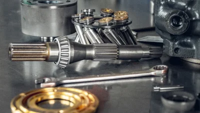
We recondition pumps, motors, and hydraulic distributors using only proven parts and modern machinery. Each repaired element is subjected to rigorous load tests on a diagnostic station before being remounted. We restore factory performance to hydraulic systems of the most popular construction machinery brands. We care for execution precision, which translates into longer life and smoother operation of the entire system.
LICCON fault codes: Central Units ZE 2 and I/O Module 2 (E/A 2)
| Fault code | Fault description / Reaction / Troubleshooting | Plug | Page | Category / Type |
|---|---|---|---|---|
| M00200001 | ZE 2: OS-HC11 system error - processor register initialization error. Reaction/Remedy: Crane operation impossible. If error recurs, replace Central Unit ZE 2. |
- | 129 | E/2 |
| M00200002 | ZE 2: OS-HC11 system error - invalid EPROM/FLASH checksum. Reaction/Remedy: Operation impossible. Check program memory card or ZE 2 unit. |
- | 129 | E/2 |
| M00200006 | ZE 2: OS-HC11 system error - RAM memory damage. Reaction/Remedy: No control possible. Replace Central Unit ZE 2. |
- | 129 | E/2 |
| M00200007 | ZE 2: OS-HC11 system error - UART controller failure. Reaction/Remedy: Operation locked. Replace ZE 2 unit if error recurs. |
- | 129 | E/2 |
| M00200010 | ZE 2: OS-HC11 system error - unavailable system procedure. Reaction/Remedy: Entry into error memory, all crane movements will be stopped. |
- | 129 | E/2 |
| M00200011 | ZE 2: OS-HC11 system error - ZE Watchdog system timeout. Reaction/Remedy: Stopping crane movements. Check power supply and ZE 2 module. |
- | 130 | E/2 |
| M00200012 | ZE 2: OS-HC11 system error - invalid type identification in EPROM. Reaction/Remedy: Operation impossible. Check software program memory card. |
- | 130 | E/2 |
| M00200013 | ZE 2: OS-HC11 system error - FLASH checksum error. Reaction/Remedy: Stopping operation. Inspect memory card in ZE 2 unit. |
- | 130 | E/2 |
| M00200014 | ZE 2: OS-HC11 system error - program is already running. Reaction/Remedy: Entry into error memory, stopping crane movements. |
- | 130 | E/2 |
| M00200015 | ZE 2: OS-HC11 system error - program unavailable. Reaction/Remedy: Stopping crane movements. Reload system software. |
- | 130 | E/2 |
| M00210012 | ZE 2: Output 0 - short circuit to ground. Reaction/Remedy: Output blocked. Check harness and solenoid valve coil connected to plug X72 pin 16. |
X72:16 | 136 | E/1 |
| M00210013 | ZE 2: Output 0 - open signal circuit. Reaction/Remedy: Check wire continuity from plug X72:16 to receiver. |
X72:16 | 136 | E/1 |
| M00210014 | ZE 2: Output 0 - short circuit to supply voltage (+24V). Reaction/Remedy: Remove short circuit in electrical harness of plug X72:16. |
X72:16 | 136 | E/1 |
| M00210058 | ZE 2: Output 0 - positive switching transistor: open/damaged. Reaction/Remedy: Internal damage to ZE 2 output board. Replace module. |
X72:16 | 136 | E/1 |
| M00210060 | ZE 2: Output 0 - safety chain error, diode damage, or welded contact. Reaction/Remedy: Error message. Check protective diode and contactor contact. |
X72:16 | 137 | E/1 |
| M00210070 | ZE 2: Output 0 - damage to output measurement system. Reaction/Remedy: Crane operation impossible. Entry into error list. Check output board. |
X72:16 | 137 | E/1 |
| M00210071 | ZE 2: Output 0 - short circuit to ground or power transistor damage. Reaction/Remedy: Diagnose output actuator circuit X72:16. |
X72:16 | 137 | E/1 |
| M00210072 | ZE 2: Output 0 - external power supply (voltage applied from outside). Reaction/Remedy: Disconnect external voltage source connected to plug X72:16. |
X72:16 | 137 | E/1 |
| M00210073 | ZE 2: Output 0 - circuit interruption or short to power supply/ground. Reaction/Remedy: Check electrical installation of circuit X72:16. |
X72:16 | 137 | E/1 |
| M00214959 | ZE 2: No power supply to all control outputs. Reaction/Remedy: Check main fuses for output power supply on connector X72. |
X72 | 142 | E/1 |
| M00215059 | ZE 2: No power supply to output group 0. Reaction/Remedy: Check power supply flow to pin X72:12 and corresponding fuse. |
X72:12 | 142 | E/1 |
| M00215159 | ZE 2: No power supply to output group 1. Reaction/Remedy: Check supply voltage at contact X72:24. |
X72:24 | 142 | E/1 |
| M00215259 | ZE 2: No power supply to output group 2. Reaction/Remedy: Check power supply flow to pin X72:25. |
X72:25 | 142 | E/1 |
| M00215359 | ZE 2: No power supply to output group 3. Reaction/Remedy: Check power supply line on plug X72:13. |
X72:13 | 142 | E/1 |
| M00220004 | ZE 2: LSB participant address 0 - sensor signal level exceeded. Reaction/Remedy: Check mounting and initial attenuation of sensor, clean from dirt, replace. |
X635B:z14/z16 | 142 | E/1 |
| M00220005 | ZE 2: LSB participant address 0 - signal below minimum level. Reaction/Remedy: Check sensor installation, remove mechanical damage, or replace. |
X635B:z14/z16 | 142 | E/1 |
| M00220018 | ZE 2: LSB participant address 0 - permissible sensor temperature exceeded. Reaction/Remedy: Ensure operation within permissible temperature range, check cooling. |
X635B:z14/z16 | 143 | E/0 |
| M00220050 | ZE 2: LSB participant address 0 reports incorrect sensor type. Reaction/Remedy: Check address assignment on LSB screen and install correct sensor. |
X635B:z14/z16 | 143 | E/2 |
| M00220053 | ZE 2: LSB participant address 0 not reporting or disconnected during operation. Reaction/Remedy: Participant deactivated. Check plugs and cable, replace sensor. |
X635B:z14/z16 | 143 | E/1 |
| M00223255 | ZE 2: LSB data transmission - connection damage, short circuit to power supply. Reaction/Remedy: Controller attempts to restart bus. Check line, sensors, and LSB fuse. |
X635B:z14/z16 | 156 | E/2 |